When you can draw a refrigeration cycle on a p-h diagram, you can easily
obtain the refrigerant characteristics through the diagram. Let's study
about "How to draw a refrigerant cycle" in series, using the
documents with courtesy of Mr. Yoshihiro, UDAGAWA, Toshiba-Carrier Corporation.
A p-h diagram for R22 in SI unit is used.
The diagram is attached to the annex at the end of "Examination Textbook
for The First and Second Class in SI unit" or "Examination Textbook for the Third Class in SI units" published by JSRAE. |
A p-h diagram is a figure with a vertical axis of absolute pressure and
a horizontal axis of specific enthalpy. It is an important diagram used
frequently for a performance calculation of a refrigerating machine.
A p-h diagram is made respectively for a specified refrigerant. It can,
of course, not be used for another refrigerant. Diagrams are made respectively
for conventional unit and SI unit
A p-h diagram has a lot of thin lines, whose names and natures are important. |
p-h diagram
| For example, an iso-specific volume line is a line on which the specific
volume has the same value. |
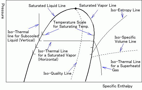
The following example is a simplified p-h diagram on which a refrigeration cycle is drawn.
Point 1 to 4 show the following.
|
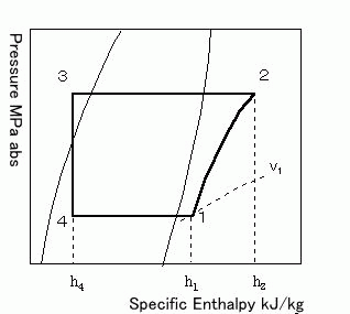
Point 1 to 2: Refrigerant change in a compressor
Point 2 to 3: Refrigerant change in a condenser
Point 3 to 4: Refrigerant change through an expansion valve
Point 4 to 1: Refrigerant change in an evaporator |
|
2. | How to draw a refrigeration cycle on a p-h diagram |
(Question)
| Draw the following refrigeration cycle on a p-h diagram. |
|
Refrigerant
|
Evaporating Temperature
|
Condensing Temperature
|
Liquid Temperature before the Expansion Valve
|
Suction Gas Temperature
|
R22
|
-15
|
30
|
25
|
-10 |
| Notice : | Conditions may be given as follows. Meanings of both are the same. |
|
Refrigerant
|
Evaporating Pressure
|
Condensing Pressure
|
Subcool
|
Superheat
|
R22
|
0.296 MPa
|
1.192 MPa
|
5
|
5
|
|
iProcedure for an Answerj |
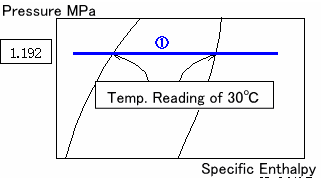
| (1) Draw a line for a condenser |
Draw a horizontal line (1) crossing both on a saturated vapor line and
saturated liquid line at 30. The length of the line is adjusted later.
Shorter the line is, easier adjusted. |
A horizontal line passing through a condensing pressure of 1.192 MPa for
30 is same as the above line. |
 |
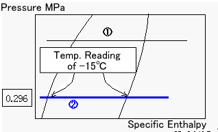
| (2) Draw a line for an evaporator |
Draw a horizontal line (2) crossing both on a saturated vapor line and
saturated liquid line at -15. The length of the line is also adjusted
later. |
A horizontal line passing through a condensing pressure of 0.296 MPa for
-15 is same as the above line. |
 |
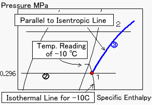
| (3) Draw a line for a compressor |
An intersection point (Point 1) of the line for an evaporator (2) and an
isothermal line for -10 shows a position of a suction gas to a compressor.
Draw a curve (3) from Point 1 parallel to an isentropic line. An isentropic
line is a curve.
|
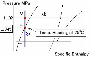
| (4) Draw a line through an expansion valve |
Since the refrigerant is a subcooled liquid of 25, draw a vertical line
(4) that passes through a saturated liquid line for 25 (Point E). An
intersection point (Point 3) of the line (4) and the line (1) shows a position
before the expansion valve. |
Point E obtained from a saturate pressure of 1.045 MPa for 25 is the
same.
|
| (5) Complete the figure |
You can draw a refrigeration cycle on a A p-h diagram as above stated.
Since it is not good to look at, please finish it like the following figure
by erasing extra lines outside of Point 1 to 4. You can read various values
from the diagram.
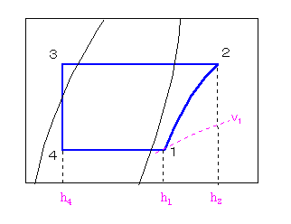 |
Have you finished drawing a refrigeration cycle on a p-h diagram well?
You can read out a specific volume (v1) and specific enthalpies (h1, h2,
h4) from the figure. |
(Answer)
A specific volume and specific enthalpies at each point |
Specific volume |
@1=0.08 m3/kgA |
Specific enthalpy |
@h1=403 kJ/kg, h2=438 kJ/kg, h4=230 kJ/kg |
| You can calculate a performance of a refrigerating machine by using these
values. |
| In the next round of this series, let's study about "Changes of refrigerant
conditions". Conditions of a refrigerant are changed by turns in a
refrigeration cycle. A typical one will be taken up. |


